We wanted some planters to put on our patio for growing flowers and vegetables. There are lots of planters of various designs for sale, but they all suffer from a simple problem that bothers me: they drip onto the patio after watering.
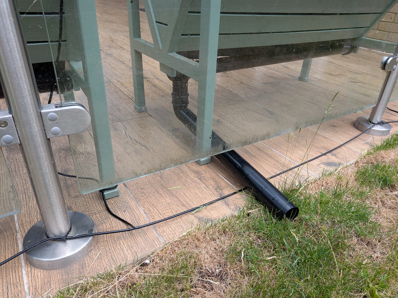
I wanted a planter with drainage that can be directed off the patio and onto the nearby grass.
I considered various designs to achieve this.
I wanted something fairly easy to build since I needed several of them.
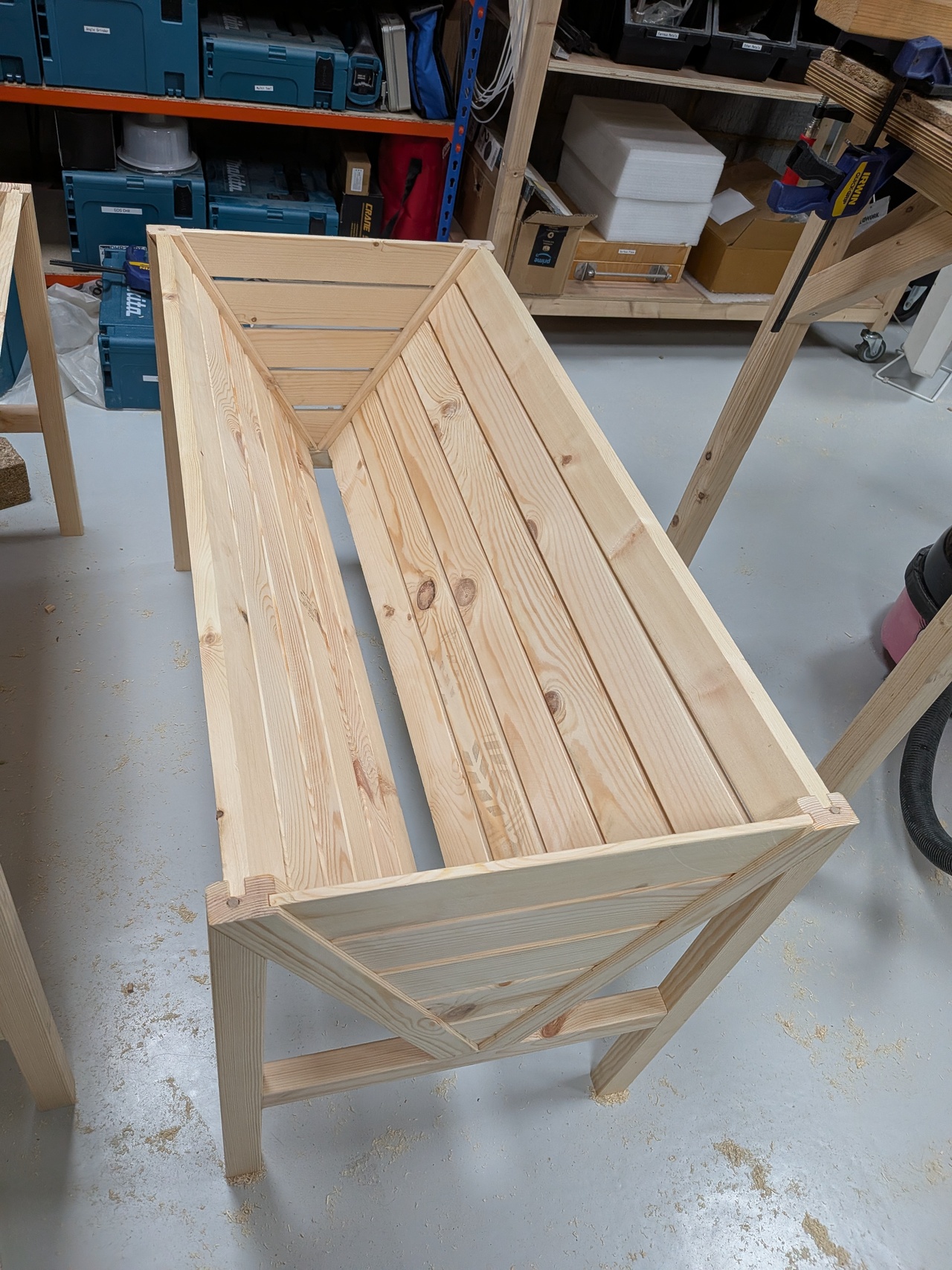
Ultimately I arrived at a triangular trough concept. With this shape, water is directed toward a line at the middle which
can then be caught and led away using readily available guttering for houses and sheds.
It needs to be unobstructed underneath for this to work so it can only be supported on the two ends
which limits the maximum span. I chose to make them 1m long.
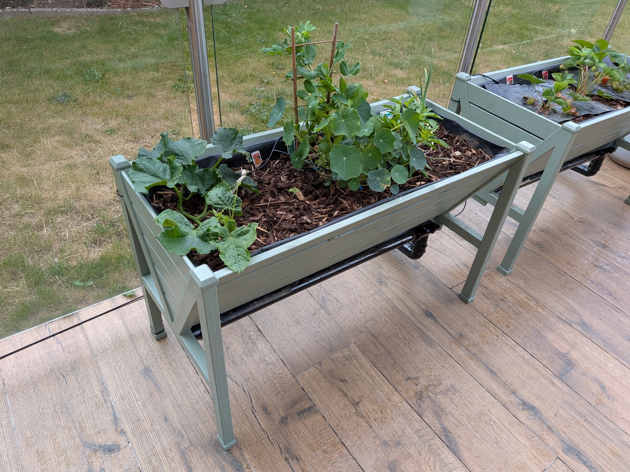
The finished planters with various vegetables growing.
I decided to build the planters from wood.
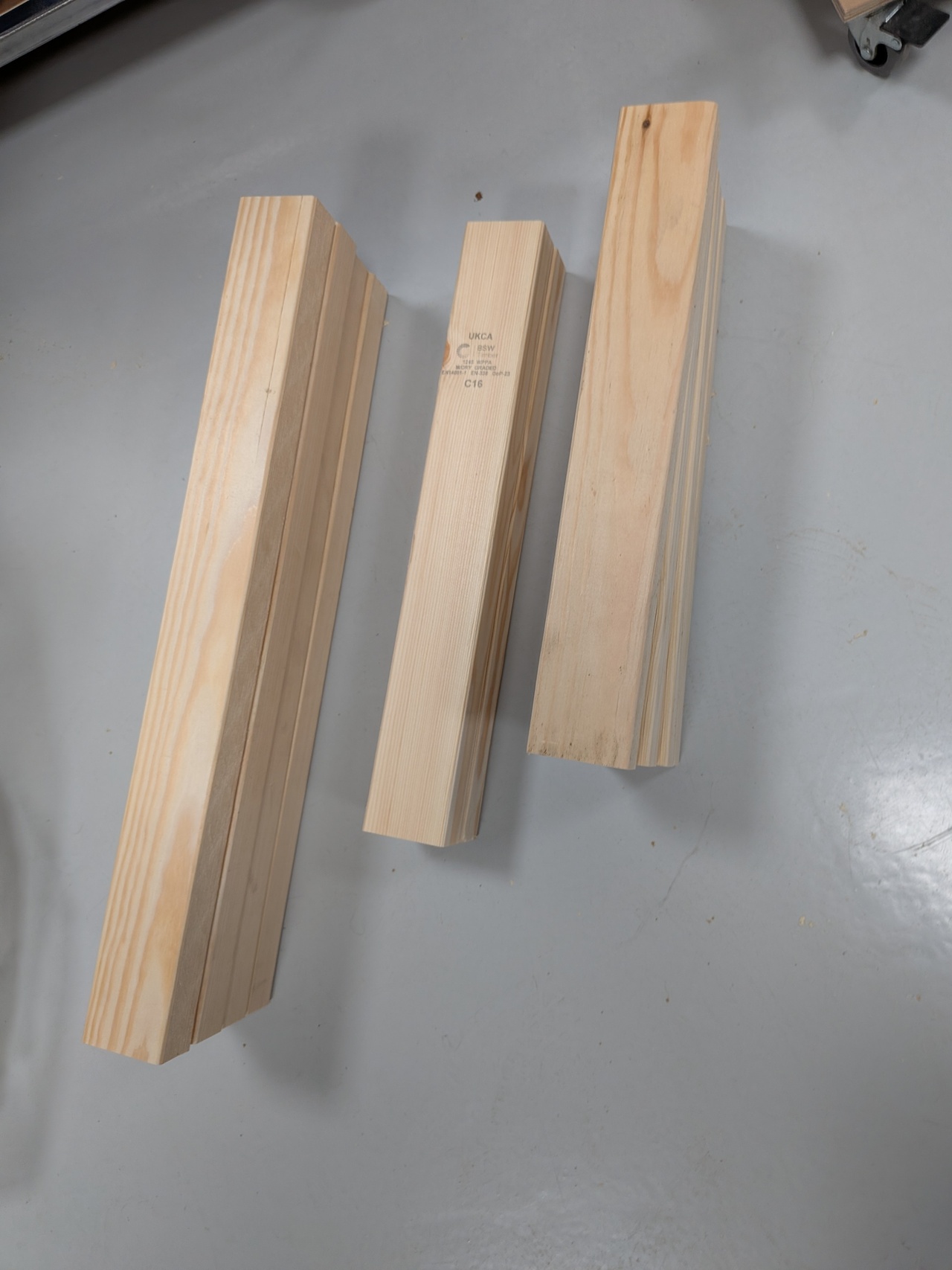
The cheapest wood available to me per unit volume is 63x38mm CLS (Canadian Lumber Standard) timber so I designed the planters around this.
Using the table saw, I can rip a length of 63x38mm CLS into either 2x 63x17mm boards, 3x 63x10mm boards, or 2x 29x38mm beams.
By constructing the project using boards of these dimensions, a single length of 63x38mm CLS goes a long way.
For these 1m long planters, just 4x 2.4m lengths of 63x38mm CLS (costing £14) is needed for each planter.
Each planter is constructed with two end frames made from 29x38mm beams, as shown in the drawing below.
These frames are joined horizontally with 63x17mm slats to form the trough.
The ends are filled in with 63x10mm slats.
I was worried that these sizes might be a bit flimsy and that the 17mm thick slats might bend over the 1m span,
but so far it seems to be holding up well and there's no noticeable deflection of the slats.
Drawing of the end frames.
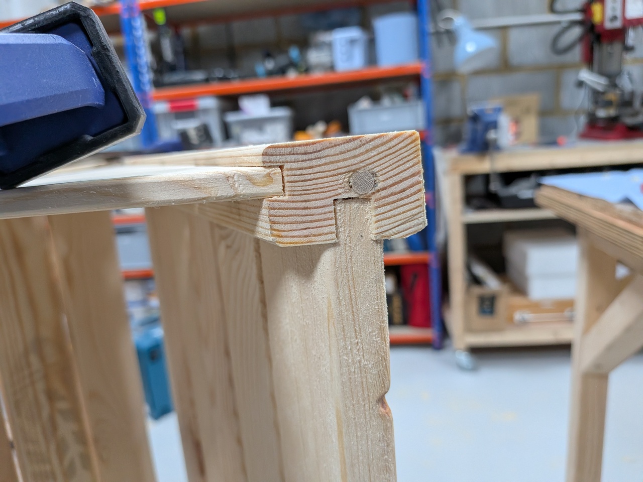
On these frames, the cross beams are joined to the posts using mortise and tenon joints. The diagonal braces are attached with dowels.
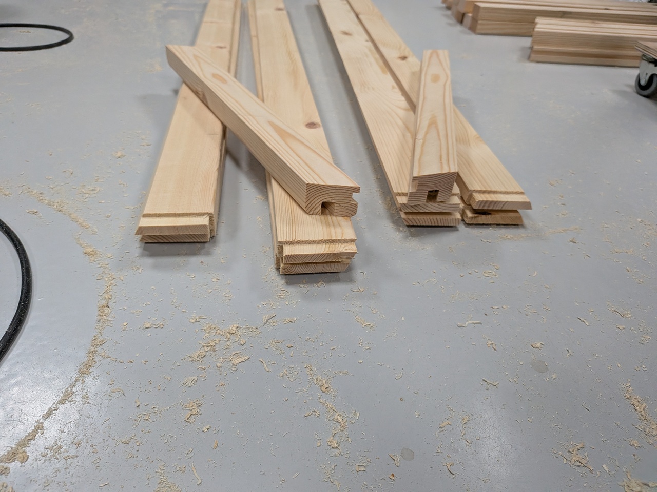
The slats sit in grooves (rebates) along the diagonal braces as can be seen in this photo:
View of the grooves and slats in the diagonal brace.
All the joints are glued with Everbuild D4 exterior rated wood glue - no screws or nails. I used untreated timber.
However, I did paint everything after assembly with a paint sprayer to reach everywhere on the inside and outside.
There is a plastic liner inside which prevents contact with the soil and water.
They will be outside all year round uncovered.
Hopefully they'll last for a few years.
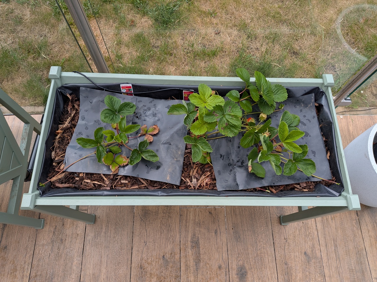
The strawberries have been delicious. Some basic irrigation has been added to automate watering.
I’m quite happy with how they turned out and how effectively the drainage has worked.
They did take longer to build than I was hoping though.
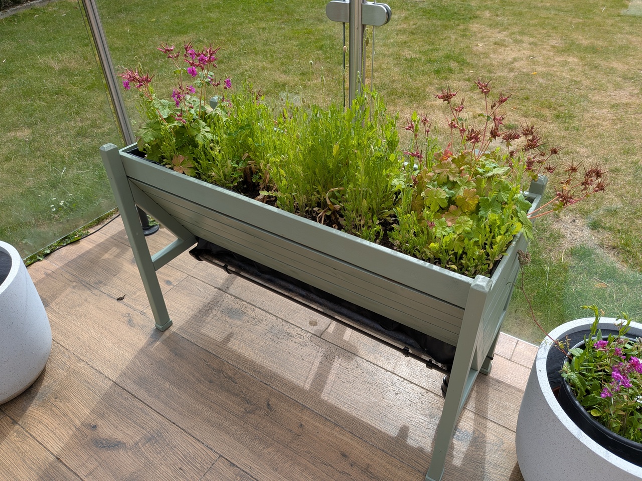
This was the second iteration of the design. The first iteration, shown below, didn't have rebates along the diagonal braces.
Instead slats were simply glued on top of the diagonal braces.
Unfortunately this required lots of awkward clamping, which had to be done in stages over several days, and I resorted to screws for some of them.
It's also probably not as strong.
It does have the advantages of not requiring caps and allowing the top row of slats to be vertical, which I think looks a bit nicer.
The first iteration had a slightly different construction.
Below is a photo album showing the build process for the two planters built according to the second iteration of the design:
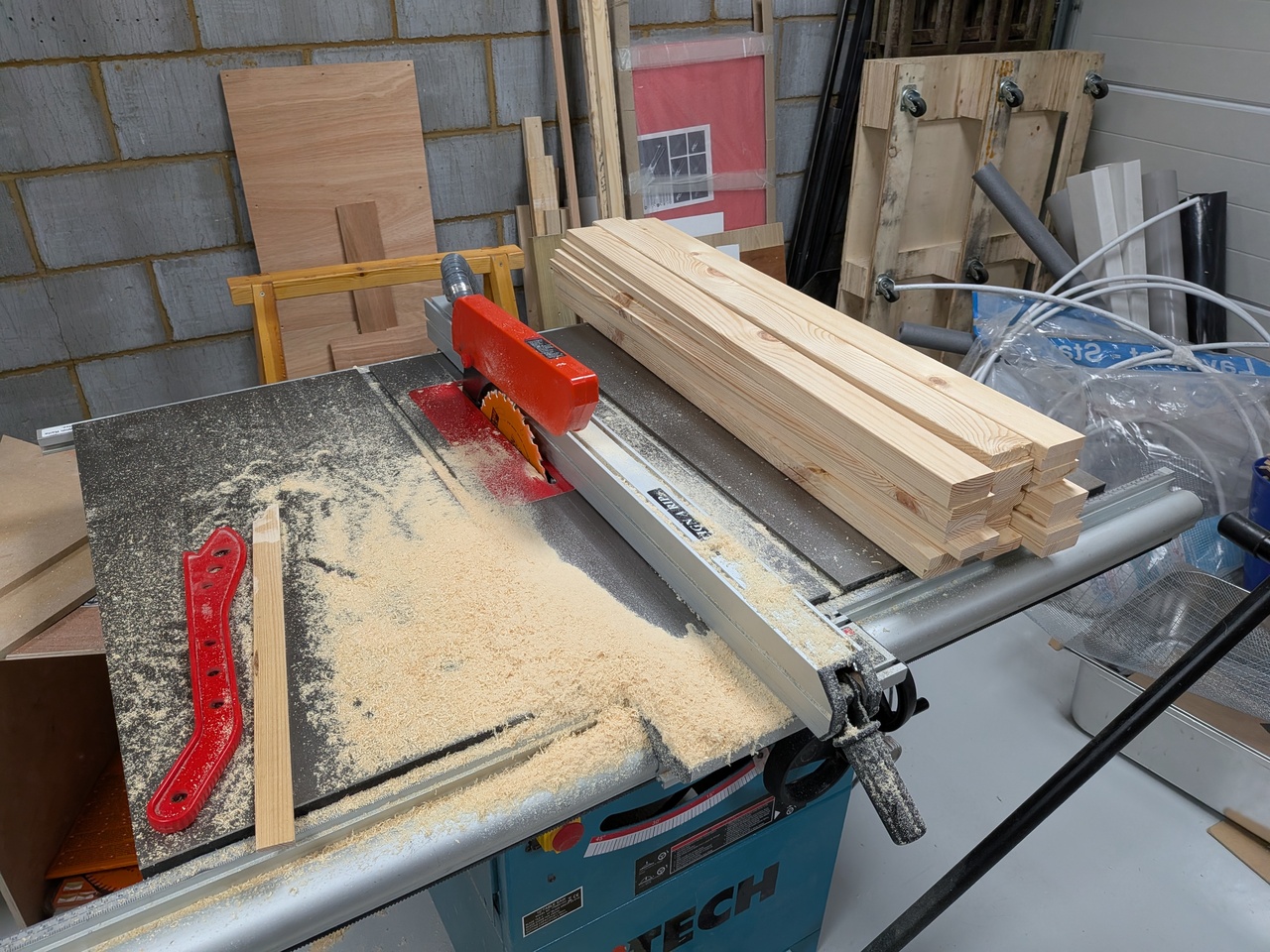
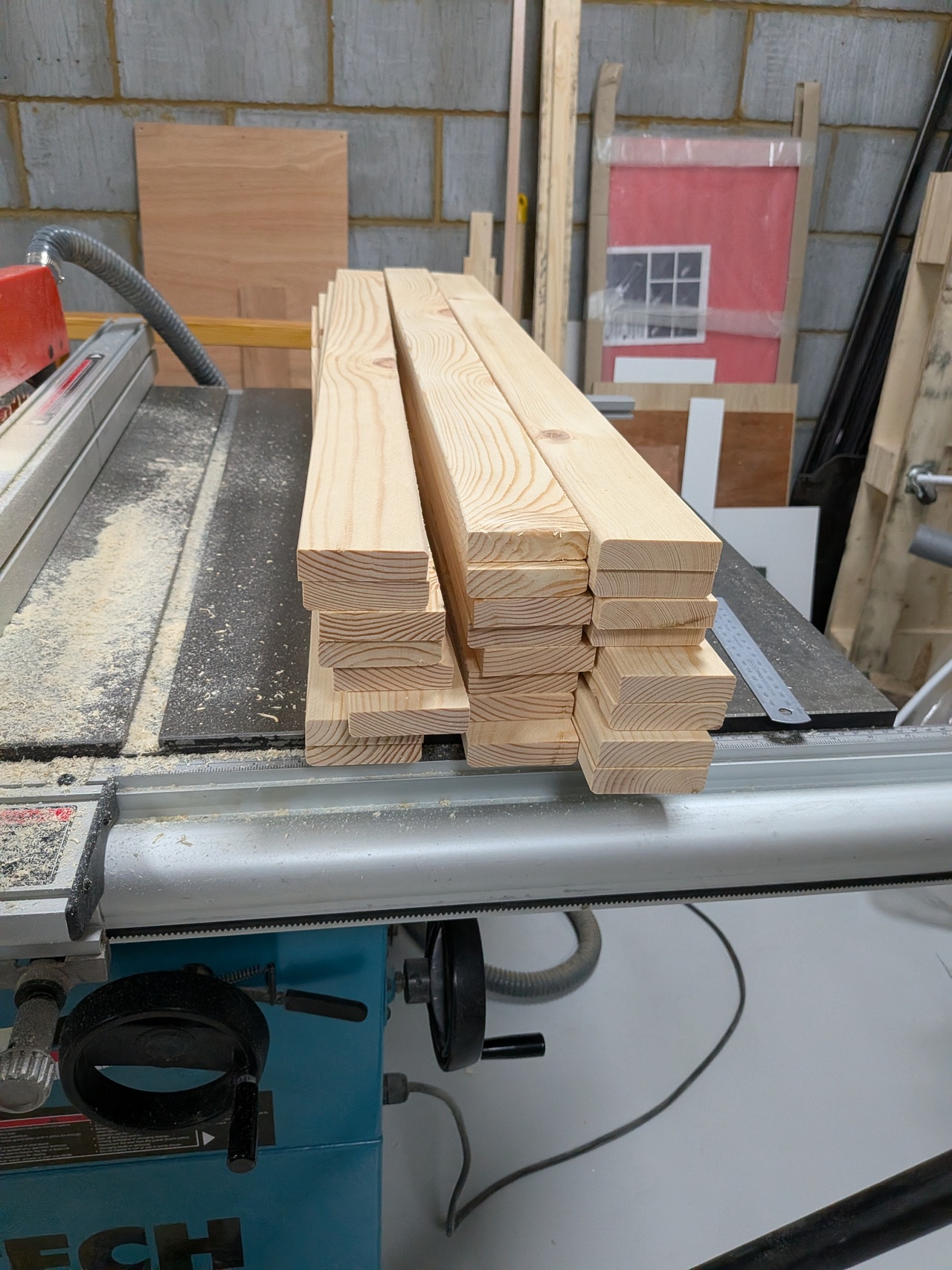
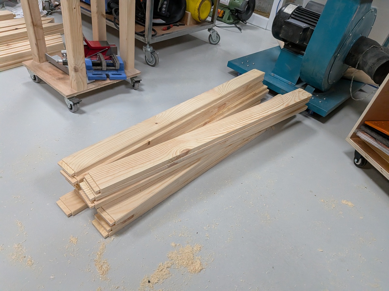
Making the frames: crosscut the CLS timbers down to approximate lengths on the mitre saw (all with square ends).
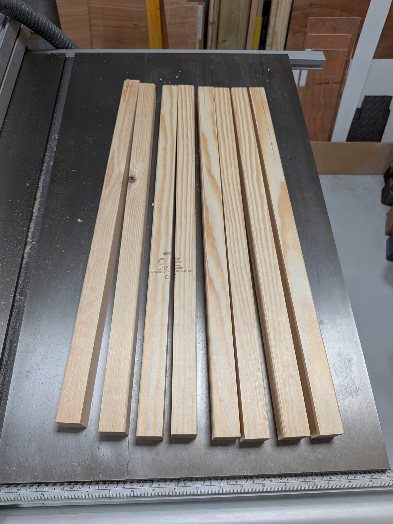
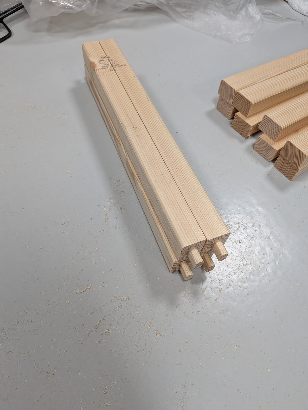
Rip the CLS pieces for the frames in half, down to 29x38mm, on the table saw.
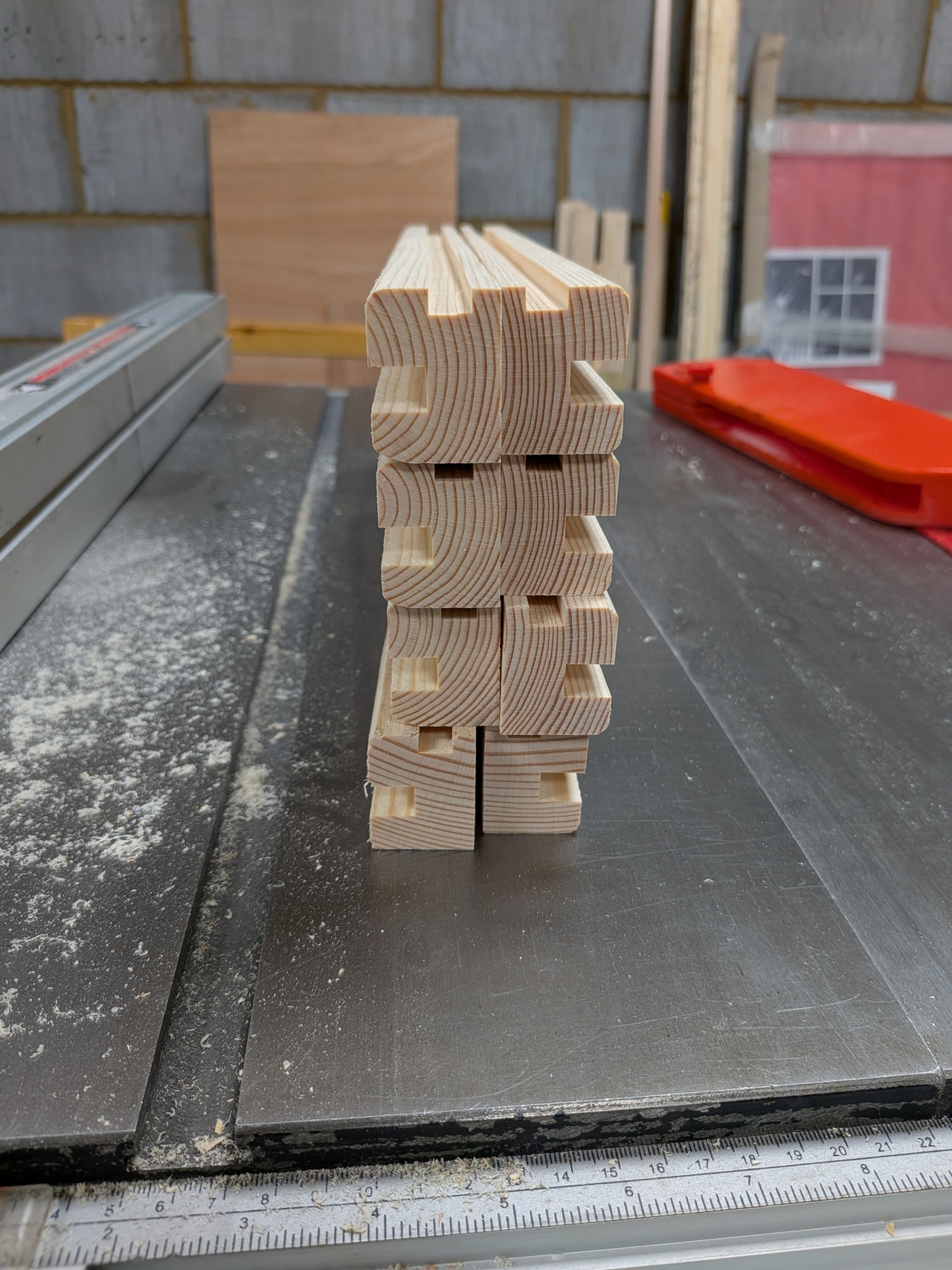
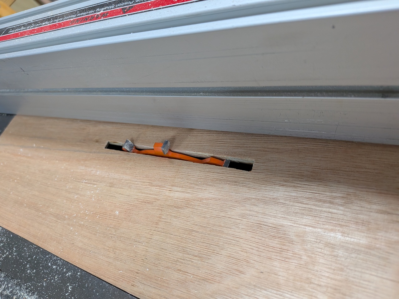
Cut grooves (rebates) on the diagonal pieces on the table saw using a 6mm grooving blade (with multiple passes to reach the desired thickness of 9.5mm).
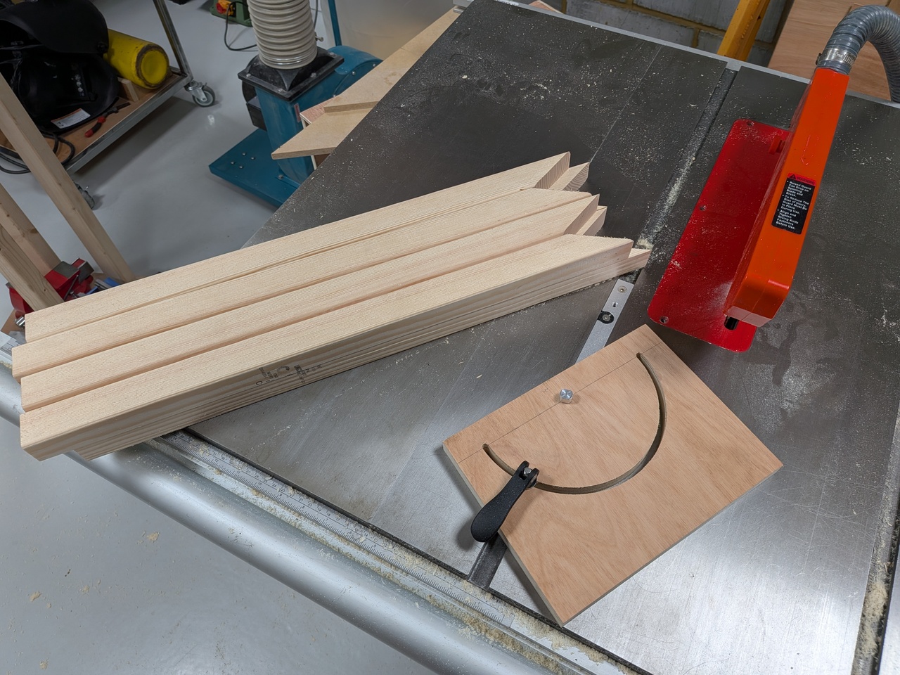
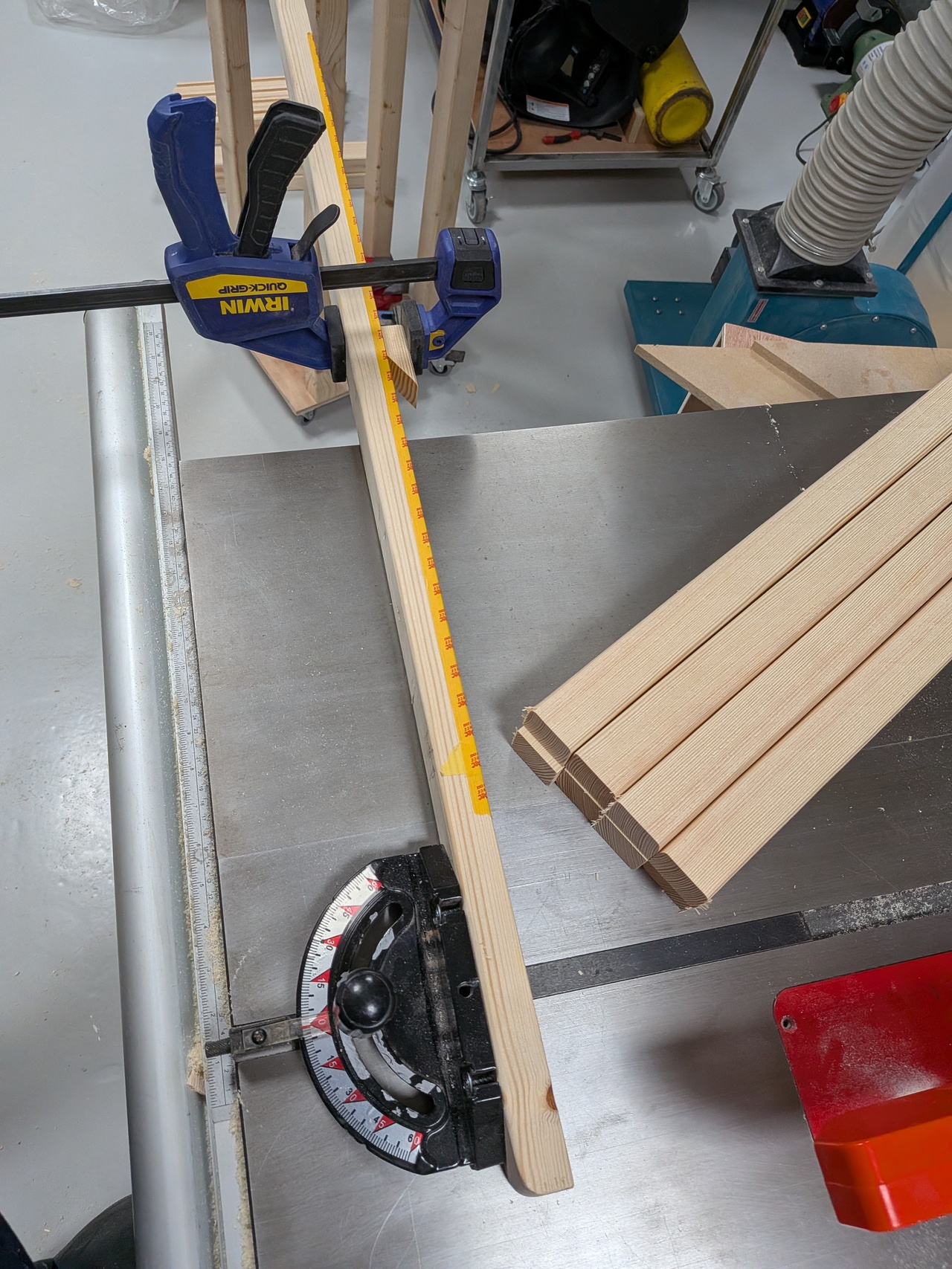
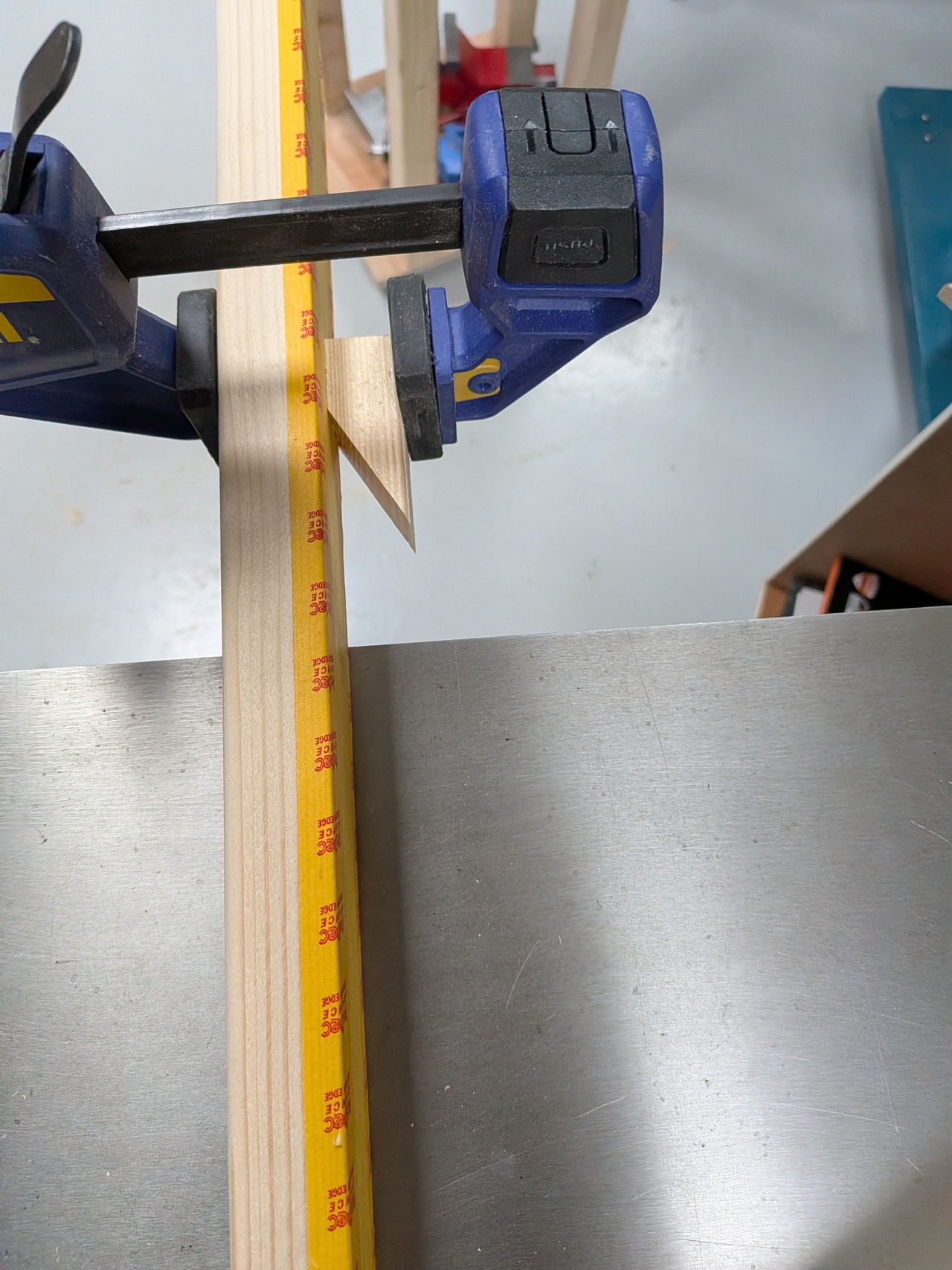
Cut the top of the posts to 60 degrees on the table saw.
60 degrees is too steep for the mitre gauge that came with my table saw (and much too steep for my mitre saw),
so I made a basic mitre gauge with extra range.
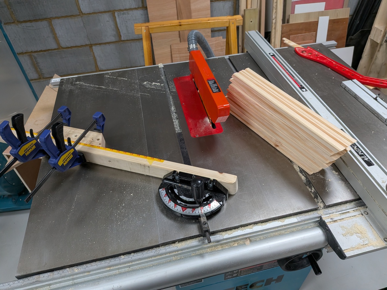
Cut 30 degree mitres on the diagonals. This time using the stock mitre gauge on the table saw with a stop block cut at the same angle.
Cross cut the bottom of the posts to final length using a stop block matching the 60 degree angle.
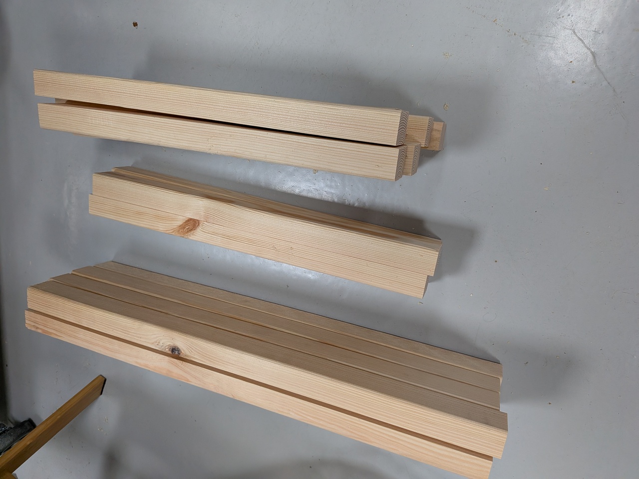
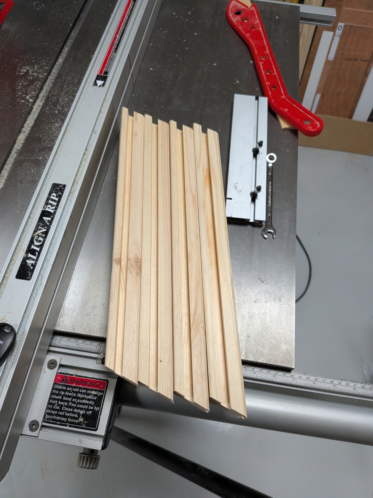
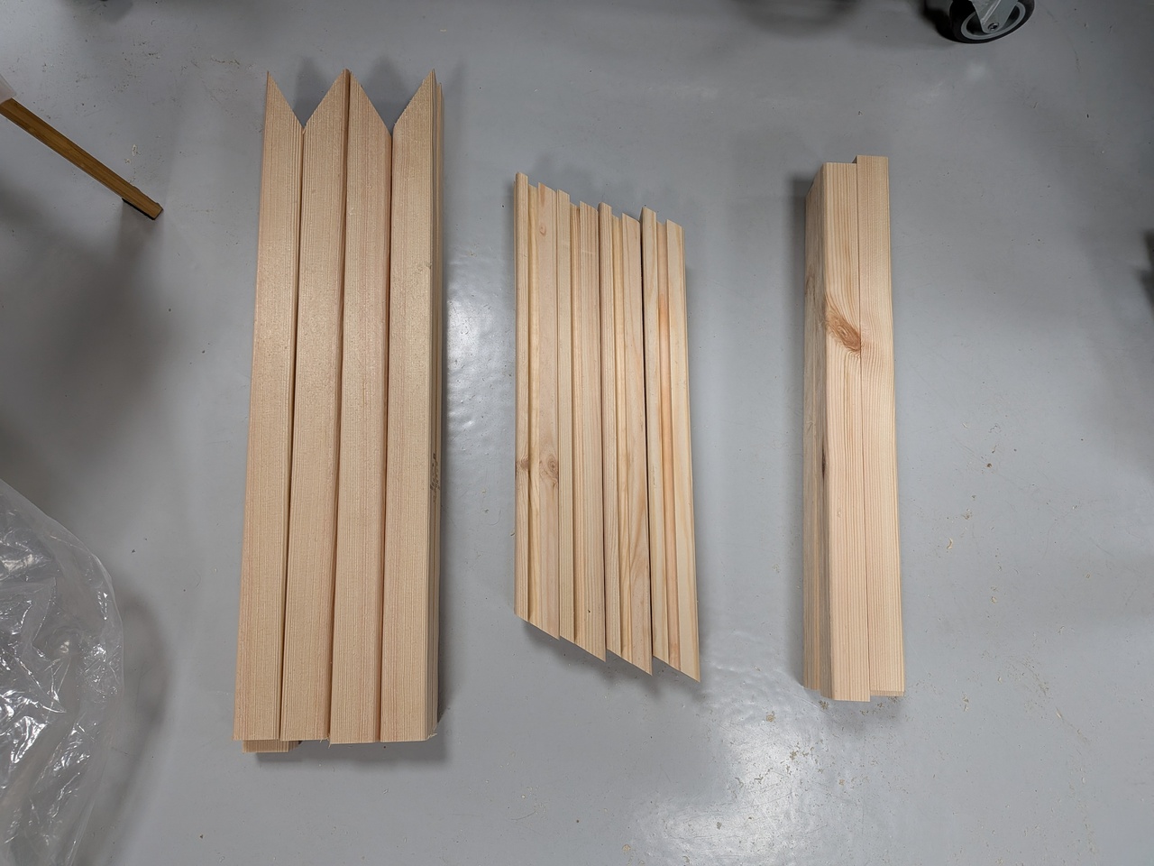
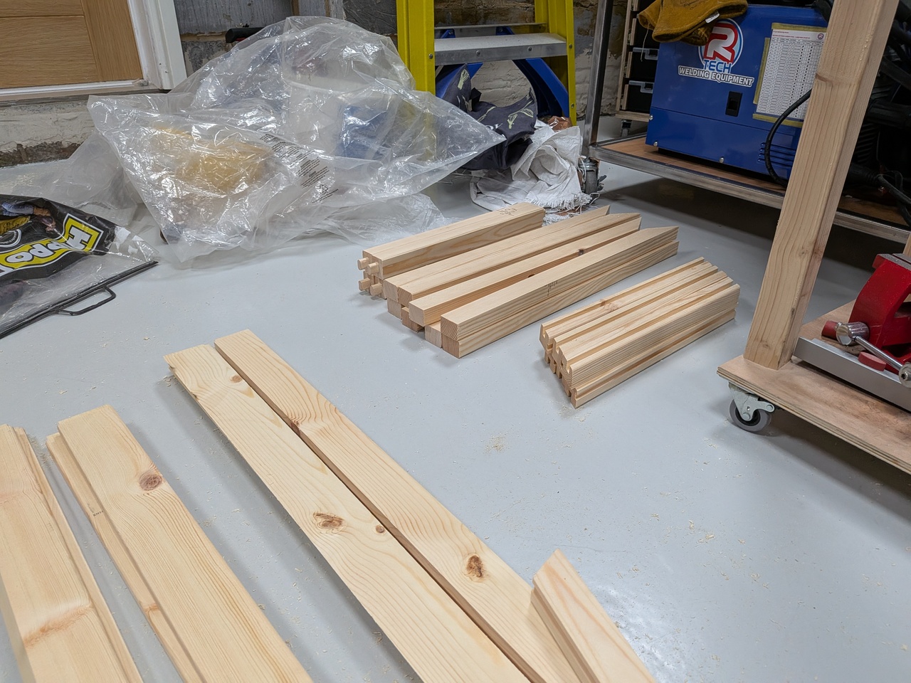
All the pieces for the frames are now cut to size and shape.
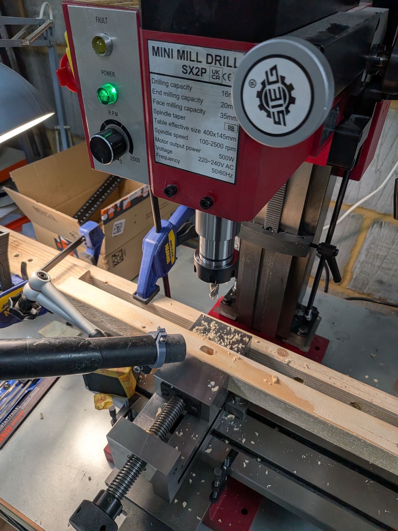
Making the mortises on the posts (where the cross beams will attach) using the milling machine and a 5/8" (9.5mm) HSS endmill.
There's a stop block to get a consistent location along the beam.
There are stops on all the machine axes. The vacuum cleaner nozzle is positioned with a magnetic dial indicator stand.
It took some time to setup but cutting each mortise is quick.
The tenons on the frame cross beams are cut on the table saw.
The corners are rounded manually using a chisel.
Getting the fit just right is tricky because blade height adjustment on my table saw is not very precise.
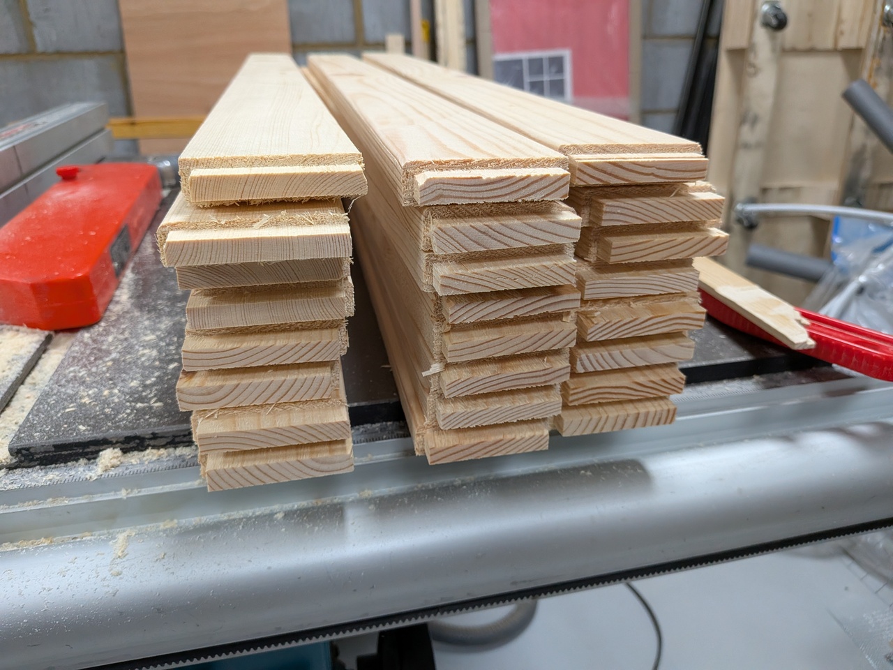
The slats for the sides are first crosscut on the mitre saw and then ripped down to 63x17mm on the table saw.
Forming tenons on the ends of the slats to slot into the diagonal brace grooves.
Remembering to leave the edges on the top and bottom slats uncut since they must be flush with the ends of the diagonal brace.
The top and bottom slats get a 30 degree bevel to match the mitred ends of the diagonal braces.
All parts complete and ready for assembly.
The edges have all been rounded over where needed using a router or sanding (on the bevelled edges).
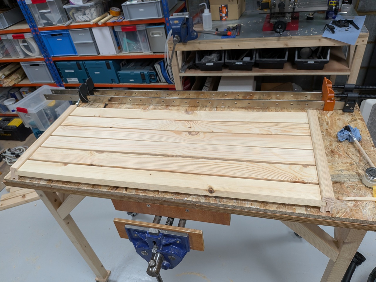
Test fitting one side panel.
Not visible here, but there are small spacer blocks that fit between the slats in the groove to give consistent gaps.
They don't fall out while assembling because they are partially covered by the shoulders of the slat tenons.
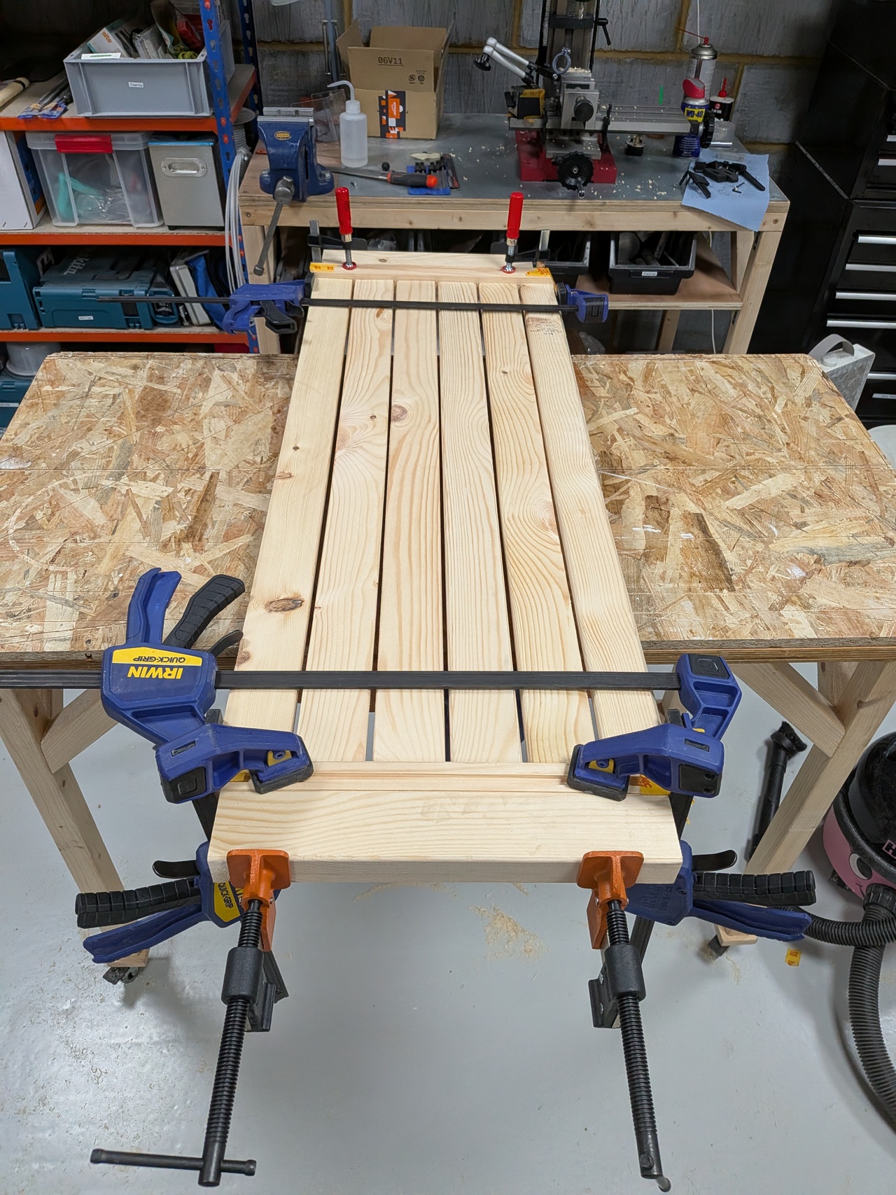
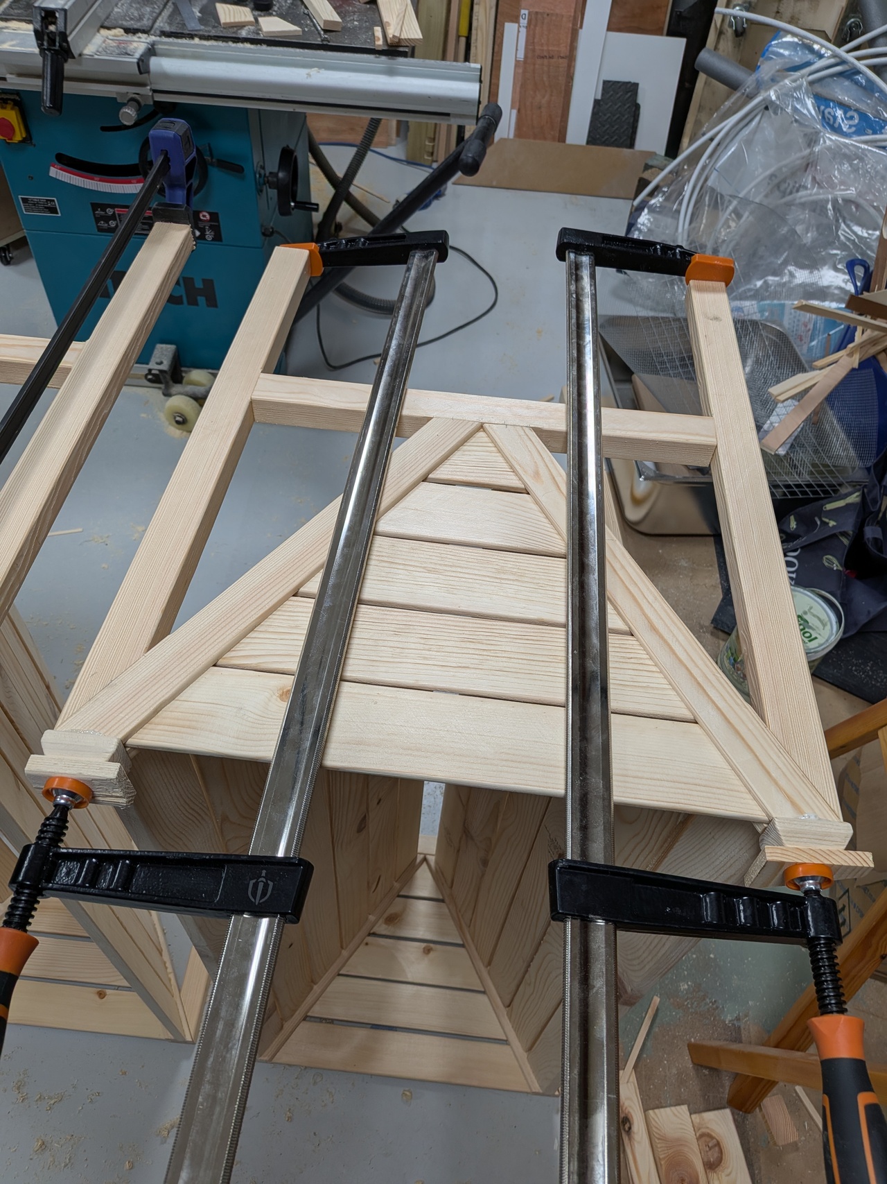
Glueing up a side panel.
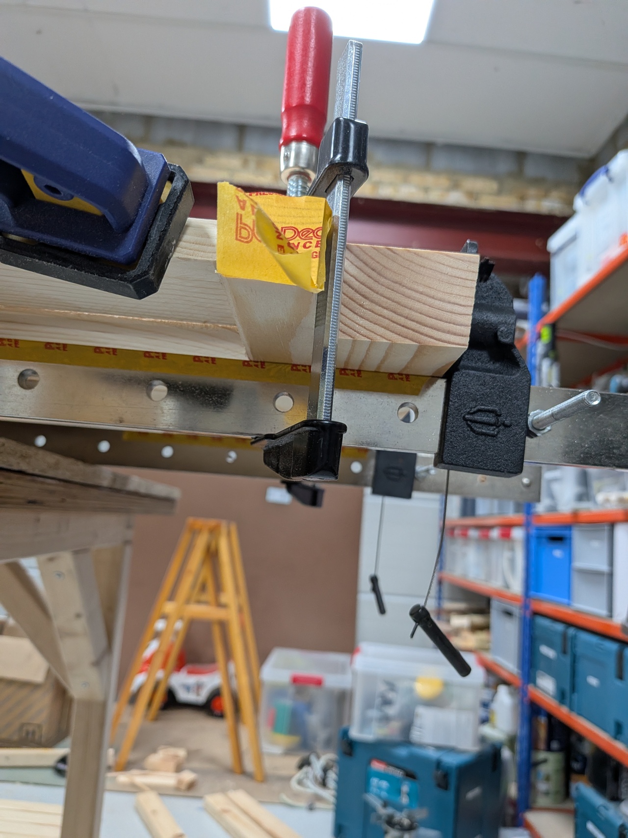
Two long sash clamps on the bottom provide the main clampage.
A spreader block with a slight bevel counteracts the clamps' tendency to pivot up.
There are quite a lot of parts to glue and the D4 glue sets quickly, so I had to work fast.
On one of the panels, one of the slats jammed slightly out of place and I wasn’t able to correct it because the glue had already started drying.
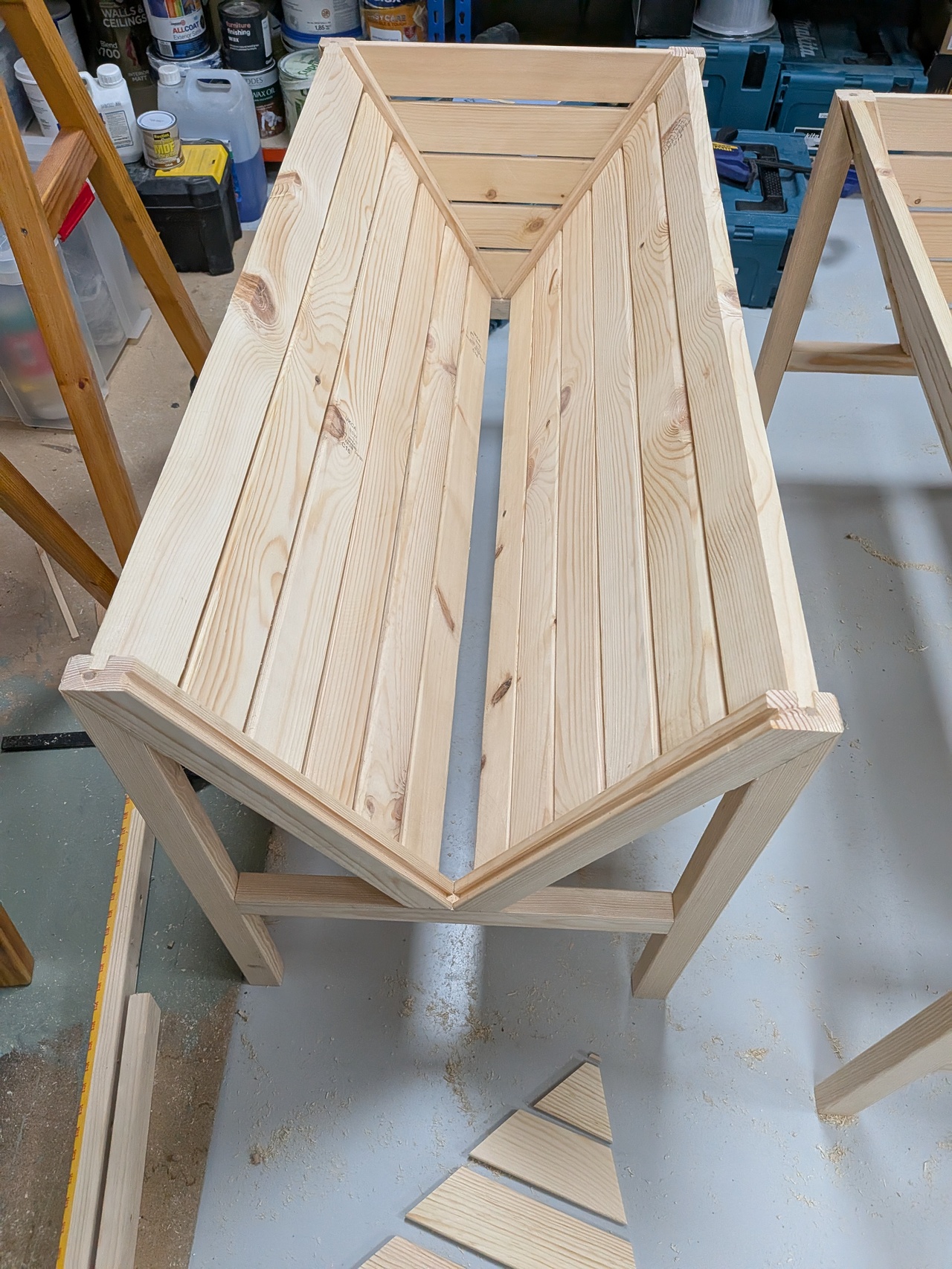
Glueing up the frames and panels. These are all glued in one go so again we have to work fast.
I didn't have time to take photos, so this shows it a bit later (while I was test fitting the end slats).
The procedure for gluing is
1) glue up two end frames,
2) stand them up in approximately the right distance apart with a couple of clamps so they don't fall over,
3) place one side panel,
4) place the other side panel.
At this point the panels can balance without any clamps while their positions can be fine-tuned and dowels inserted (next step).
The diagonal braces are attached to the frame using dowels.
I wasn't able to pre-drill the holes on both pieces accurately enough, so instead I drilled one side of the joint only before gluing
(on the bottom of the cross beam and on the top face of the diagonal brace).
Then after putting the panels in place, I drilled through the existing hole into the opposite beam.
Then dowels can be inserted with glue and some clamps applied.
I again had an issue with glue drying too fast in one case - I didn't close one of the dowel joints fast enough and it got stuck with a small gap between the pieces.
After the glue has dried, the dowels are cut off flush with the surface.
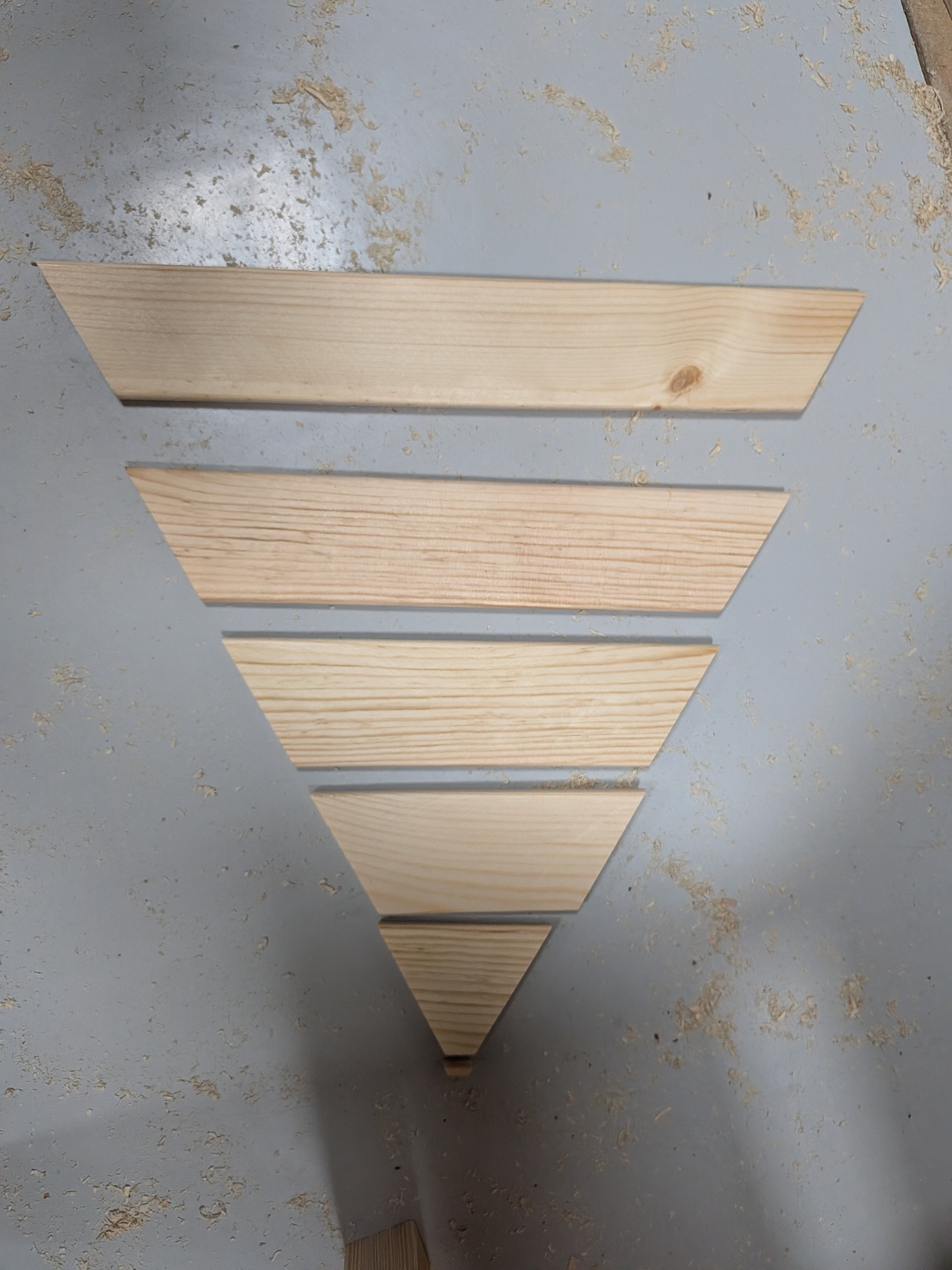
The end slats can be made from the remaining offcuts of CLS.
These are 63x9.5mm so that 3 can be ripped out of a single piece of CLS on the table saw.
They are then cut to length on the mitre saw with a 30 degree mitre.
I just marked out the lengths by measuring against the assembly piece by piece.
Gluing in the end slats. Due to the triangular taper, these don’t require clamping.
I just used a clamp to wedge them into place and then removed the clamp.
The taper also means that spacers are not necessary (unlike the side panels).
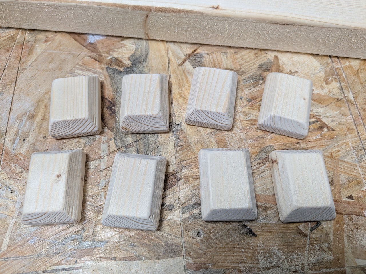
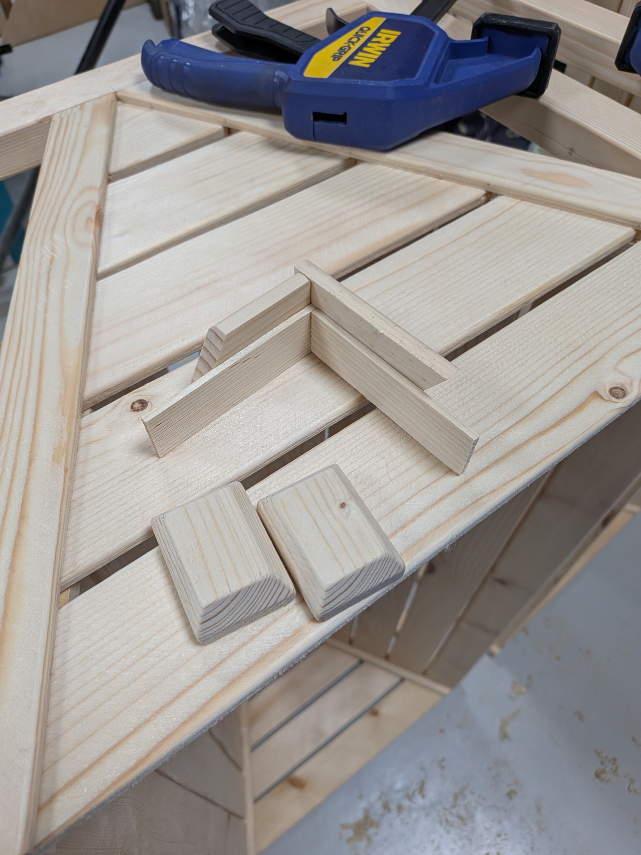
Making decorative end caps to hide the joints and dowel on the top corners.
These were made with several cuts on the table saw, rounding the bottom edges with a router and then sanding to smooth the remaining edges and corners.
There is some tearout from cutting the bevels on the table saw (when the bevel being cut intersects an existing bevel).
Gluing on the end caps. I used polyurethane glue for these.
I made a little jig to position them consistently while clamping.
Making feet for the posts.
The theory is that these will prevent the end grain from sitting in a puddle when it rains.
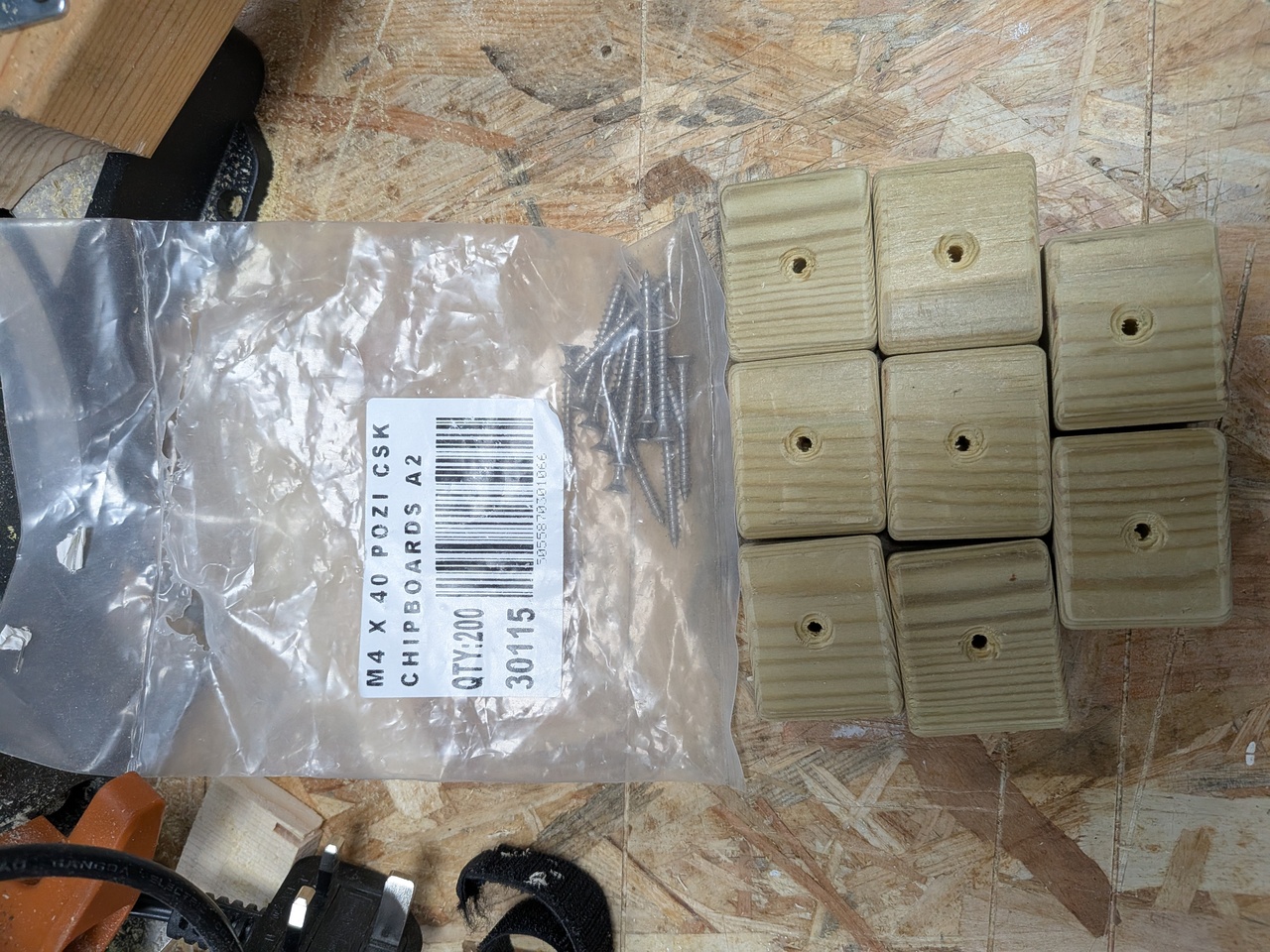
The feet are made from treated timber and screwed on with a single countersunk stainless screw.
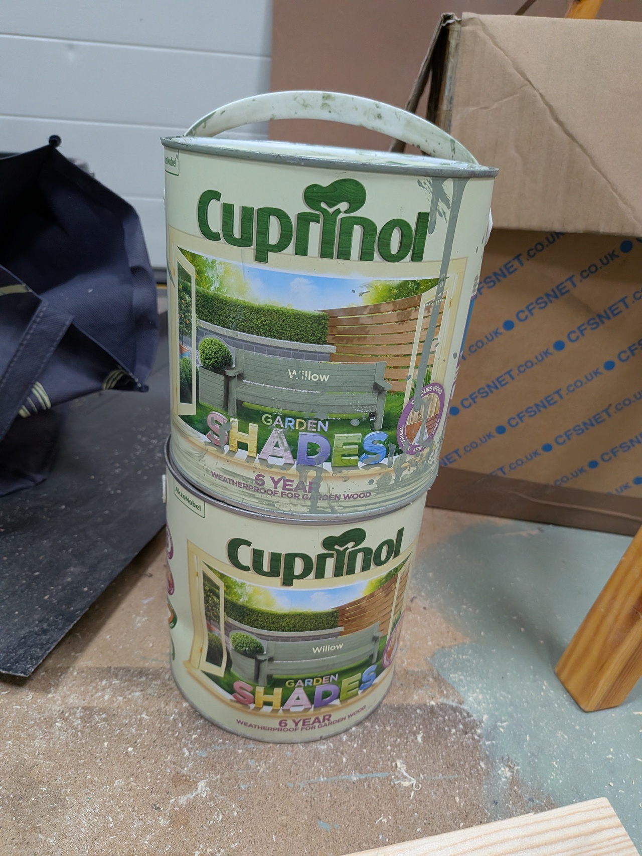
I applied two coats of Cuprinol Garden Shades using a garden fence paint sprayer on both the inside and outside.
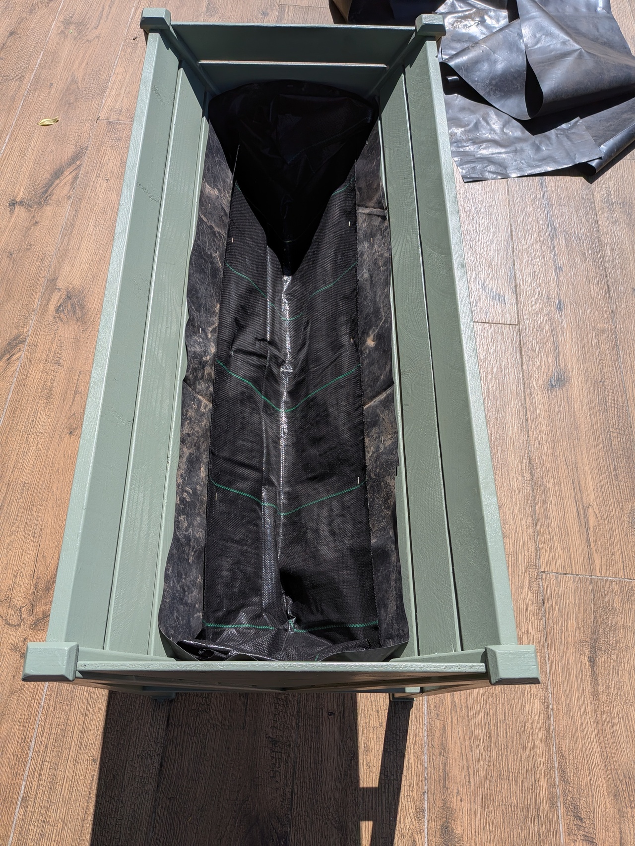
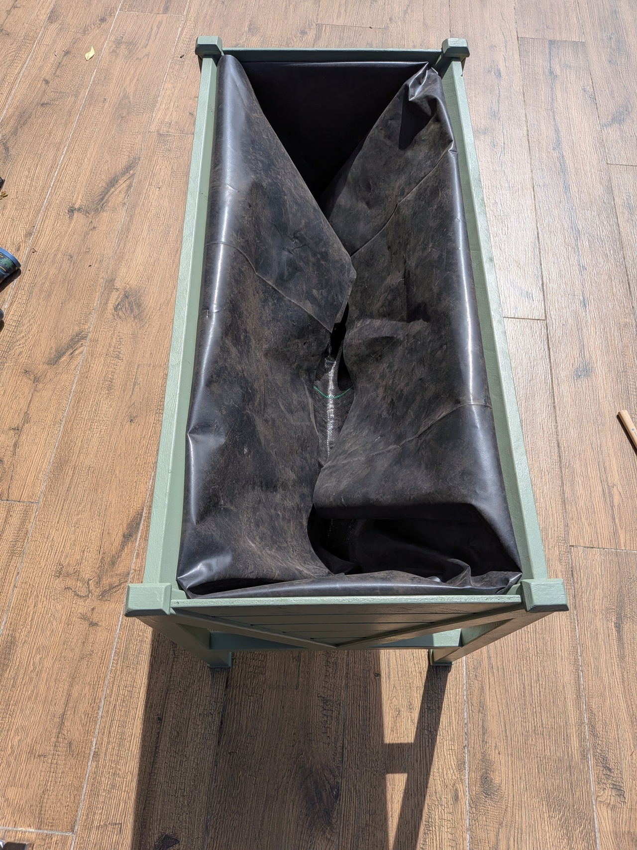
The insides are lined with three layers. A cross section drawing is shown above.
The bottom layer (C) is a waterproof plastic sheet along the sides, open at the bottom for the water to drain out.
The middle layer (B) is a semi-permeable membrane that allows water to drain out but keeps the soil in.
The top layer (A) is another waterproof plastic sheet along the sides.
They are stapled onto the slats with stainless staples.
The top sheet (A) is folded over at the top to hide the staples.
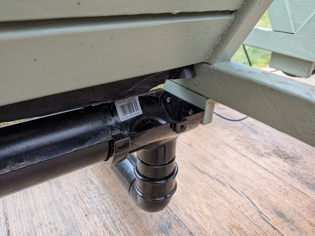
76mm PVC shed guttering is attached using some bracket blocks beneath the cross beams.