I often walk into the kitchen in search of some utensil only to find the cupboard bare and a pile of dirty ones in the sink. My only hope is then to find a clean one still packed in the dishwasher. Unfortunately, here lies a grave danger.
You see, our dishwasher is quite old and has only a limited cleaning capacity. To ensure that the dishes are cleaned properly, we have to do some of the cleaning ourselves by rinsing off the dishes first. Here is the problem: it is easy to mistake a rinsed utensil for a clean utensil.
The consequences of such a mistake can be disastrous. My experiences of this scenario have made me weary of the machine. The fear has often caused my utensil searches to terminate prematurely and unsuccessfully.
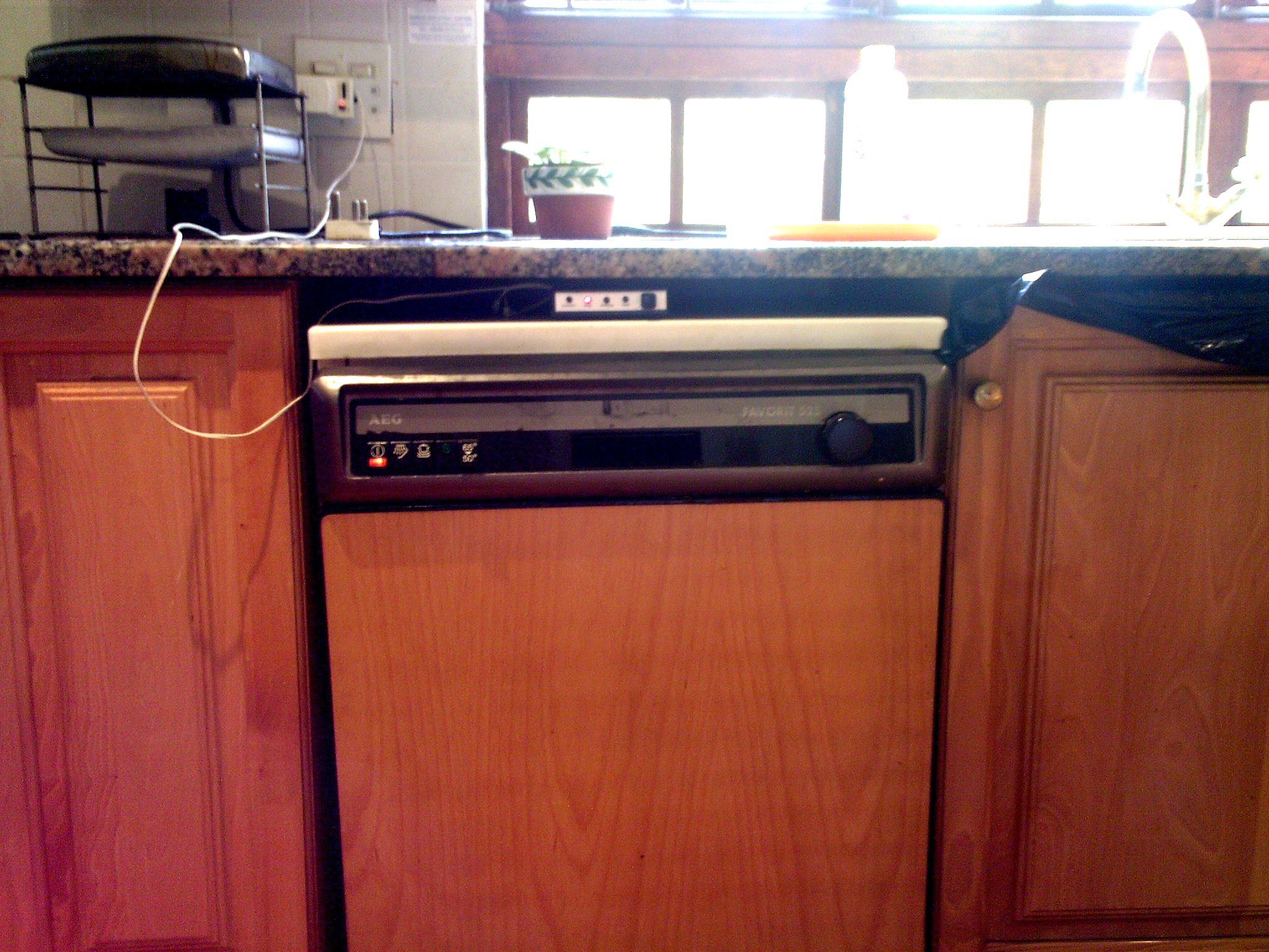
I resolved to build a small device to aid me. It would be placed above the dishwasher and indicate the state of the dishes through four LEDs labelled “Unknown”, “Dirty”, “Washing” and “Clean”. It is the responsibility of the dishwasher operator to select the correct state by means of a button.
The circuit was designed around a 4017 decade counter IC. I added a 555 timer wired in its flip-flip mode to get the states to cycle in this order:
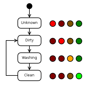
I added another 555 timer wired in its astable mode to make the “Washing” indicator blink so that the operator would remember to select the “Clean” state after the washing was finished.
Here are links to datasheets for the ICs:
In hindsight, it would have been better to use a single microcontroller than all these separate ICs.
Here is the schematic:
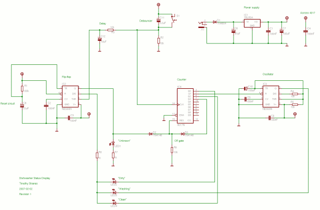
The delay network consisting of R3 and C12 is there to cause the 4017 to be enabled a few milliseconds after the button is pressed. This is needed because the button press also clocks the 4017. Without the delay, the 4017 could enable and clock simultaneously causing the state to change to “Washing” instead of “Dirty”.
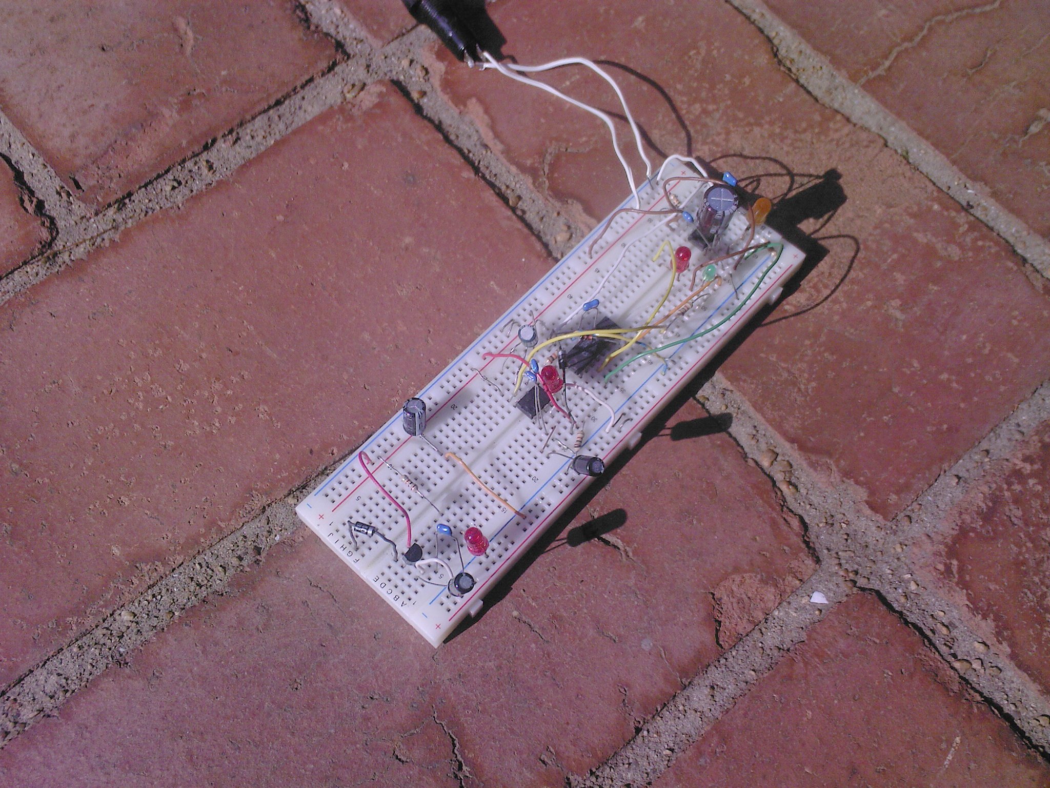
I tested the circuit on a breadboard before building the board:
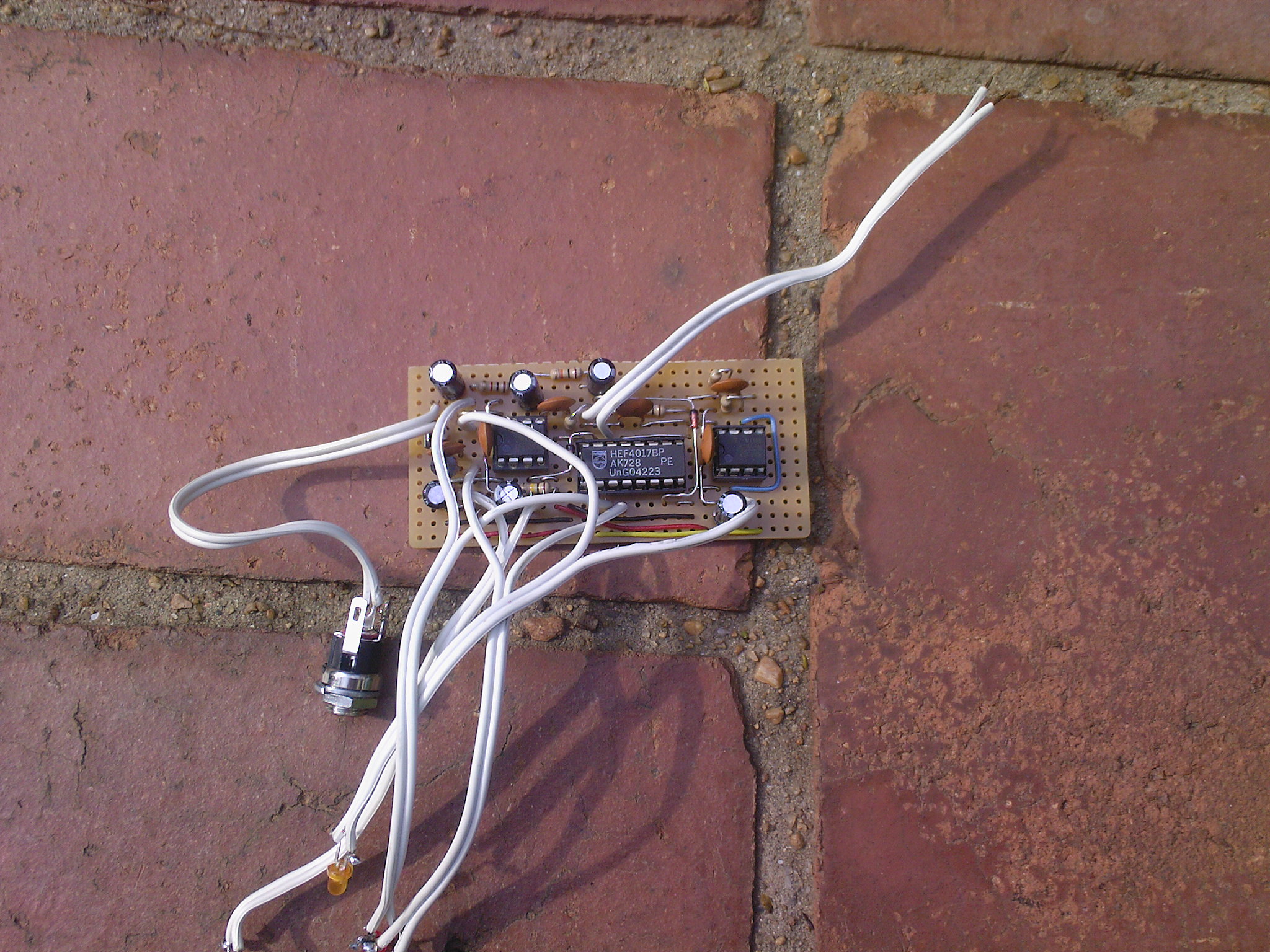
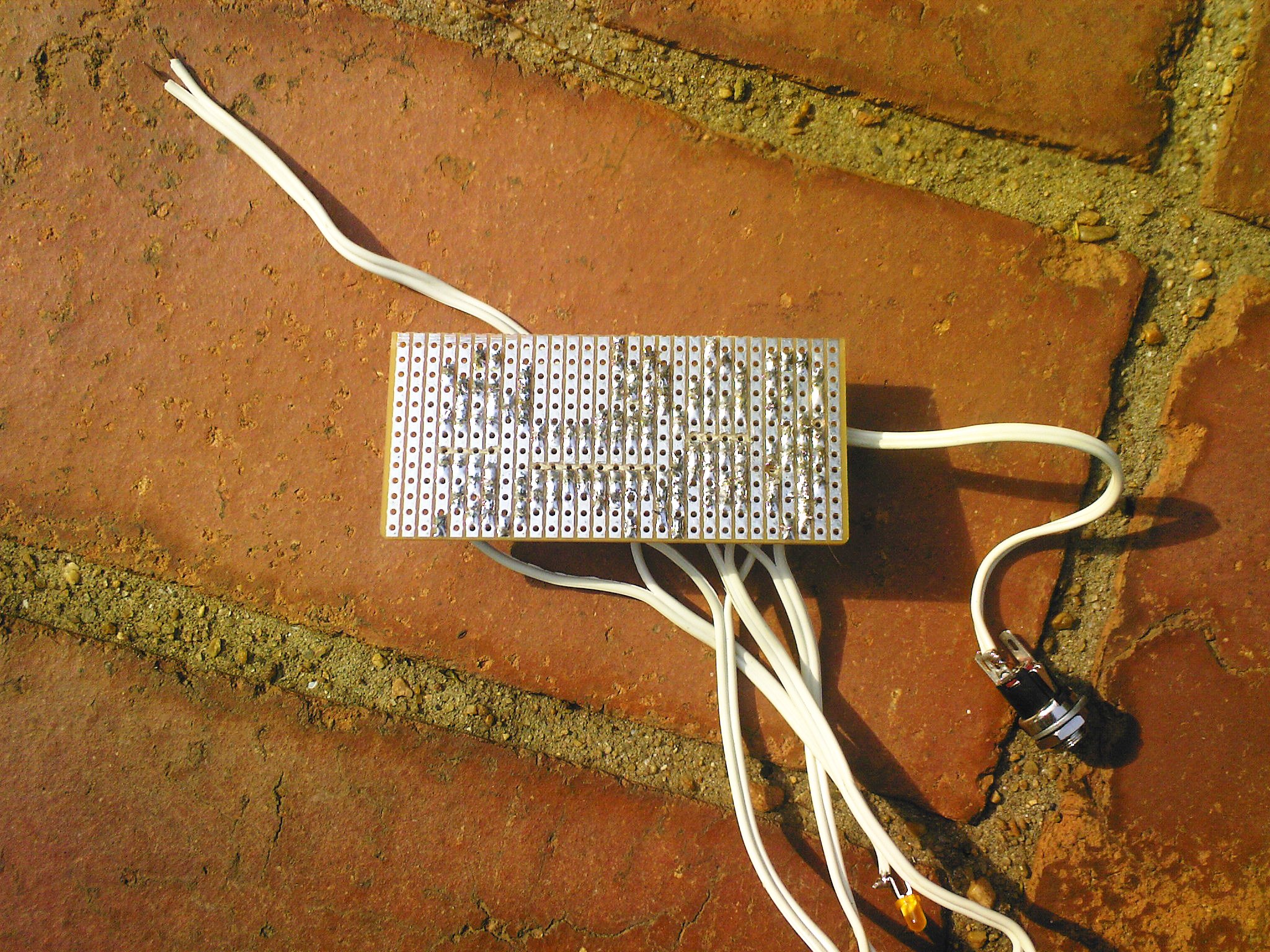
I decided to build the circuit on a piece of stripboard. It took quite some time to put together because I was trying to make it as compact as possible. It worked correctly the first time I plugged it in.
I bought a simple plastic enclosure 25mm high, 112mm wide and 60mm deep. First, I drilled holes for the components that needed to be mounted on the enclosure. Then, I printed out front and back panel designs onto paper and glued them to the box.
Here are the front and back panel designs:
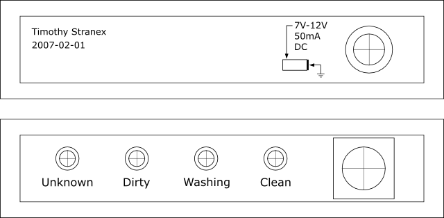
This process didn't go too well. The glue caused the paper to shrink and then expand as it dried. As a result, the panels are misaligned by about two millimetre in some places.
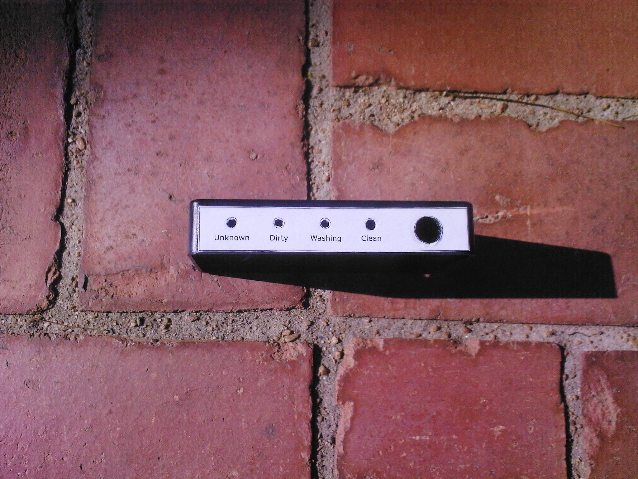
Here's how it turned out:
Just as I was finally putting everything together, I discovered that the LED holders I bought were designed for 1.1mm thick sides while the sides of the enclosure were 2mm thick. I had to carve out the extra 0.9mm with a pair of scissors: quite an unpleasant task.
I also ran into another problem: when I screwed in the pushbutton, the paper panel screwed with it. Luckily, it didn't tear.
This is how everything fitted together:
I should have made the leads shorter.